| LABORATORY/ COURSE/EQUIPMENT |
EXPERIMENT |
| ANALOG COMPUTER |
- To solve differential equations
- To simulate 1st,2nd,3rd order system on analog computer
- To simulate common non linearities-dead band, saturation, backlash etc.
- To use analog memory pair to solve split value boundary problem
|
| TRANSFER FUNCTION ANALYSER |
- Plot Open & closed loop Frequency response of feedback control system (0.001 Hz to 100kHz)
- Plot Open & closed loop Phase response of feedback control system (0.001 Hz to 100kHz)
- Obtain time domain response of feedback control systems to square and ramp waveforms
- Design compensation circuits for desired response of a feedback control system
|
| DIGITAL MULTIMETERS 3-1/2 DIGITS AND 4-1/2 DIGITS |
- To measure & compare the loading effect of a DMM and an AVO meter
- To measure the linearity of AC to DC conversion in DMM and compare it to that of an an AVO meter
- To investigate the error components in measurement of AC, DC & Resistance by DMM and AVO meters
|
| REGULATED POWER SUPPLIES |
- To develop test set for measurement of Line & Regulation of DC regulated Power Supplies & then measure the parameters.
- To measure ripple & noise in DC regulated power supplies
- To measure the effect of ground loops on the above measurements
- To measure the transient recovery time of DC power Supplies and observe its effect on switching circuits.
- To measure the output impedance of regulated power supplies.
- To measure the efficiency of series regulator and measure all components of losses and correlate
|
BASIC ELECTRONICS LABORATORY
1. NETWORK THEOREMS
2. DEVICE CHARACTERISTICS
3.POWER ELECTRONICS
4. POWER SUPPLIES
5. OSC. & MULTIVIBRATORS
6. AMPLIFIER CIRCUITS
7. WAVEFORM GENERATORS
8. DIGITAL CIRCUITS
9. OPERATIONAL AMPLIFIERS
10. FILTER CIRCUITS |
- To verify all the network theorems
- To obtain the characteristics of devices-diodes, diacs, LED’s, bipolar transistors, Junction Field effect transistors, MOSFETS, SCR’s, Triacs
- To obtain ac signal parameters from the plots obtained earlier-dynamic resistance, h parameters, transconductance etc and verify the same from published data sheets
- To determine I/P, O/P resistance; gain & phase frequency response of BJT & FET amplifiers in the three basic configurations.
- To configure amplifier in series, shunt, series-shunt, shunt-series feedback modes and measure I/P, O/P resistance; frequency response
- To configure different RC oscillators, verify the applicable frequency formula and measure frequency stability as a function of component tolerance and power supply variation.
- To configure a bistable multivibrator and obtain the highest toggle frequency as limited by 1. Device type and 2. Commutating capacitor for same device.
- To configure a astable multivibrator and 1.plot its frequency vs RC and 2. Determine its 1. Lowest & 2 fastest operating frequency
- To measure efficiency improvement by free wheeling diode in thyristor controller for RL load.
|
| LABORATORY COURSEWARE IN DIGITAL TECHNIQUES |
- A lab course in digital techniques for Junior Engineers at DOT for electronic exchanges
- A lab course in Digital Electronics for Diploma programmes in Delhi, UP, Haryana, Himachal, Punjab & Rajasthan
- A course on 8085 Microprocessors
|
| IC TESTERS |
- Measure TTL family static characteristics on IC tester
- Measure CMOS family static characteristics on IC tester
- Measure Input bias current, offset voltage, open loop gain of Op Amps on Linear IC tester
|
| LINEAR SYSTEM LAB |
- Plotting Frequency/Phase response of Operational Amplifier as Inverter, Non inverter and as Summer for different gains
- Measurement of Input Resistance of Operational Amplifier as Inverter, Non inverter and as Summer for different gains
- Measurement of Output Resistance of Operational Amplifier as Inverter, Non inverter and as Summer for different gains
- Determination of Gain Band Width product of Operational Amplifier
- Measurement of Slew Rate of Operational Amplifier
- Measurement of Common Mode Rejection Ration, Power Supply rejection ration ratio of Op Amp
- Determine the Capture range & lock range of phase locked loop
- Measure & Compare the linearity of VCO in CD 4046 and NE 565
- Measure switching time of high speed comparator NE 529.
|
| INSTRUMENTATION & PROCESS CONTROL LAB |
- Measure linearity of LVDT
- Determine Guage Factor of Strain gauge
- Measure Linearity of Angular displacement sensor and linearize it using Diode Function Generator used in Linear Systems lab
- Plot characteristics of 3 kinds of thermocouples. PTC and NTC thermistors, using PT 100 as standard.
- Plot response of LDR and photo diode and Photo transistor
- Build phase sensitive detector using:
- Diode bridge, and
- Using centre tapped transformer.
- Build discrete transistor equivalent of integrated temp sensor.
- Build signal conditioning circuit for a turbine type flow meter
- Build undernoted building blocks:
- Voltage Buffer, Instrumentation Amplifier, Differential Amplifier, power amplifier-then build as many feedback control systems out of these and available sensors in lab-e.g. light control system.
- Experiment on temperature control process with temp control of moving stream of air with PID controller. Input is the step inputs to the open-loop system to determine the nature of the transfer function between the set value and the output of the temperature sensor.
- Experiment on input as step inputs to the open-loop system to determine the nature of the transfer function between the set value and the output of the temperature sensor.
- Experiment on how the open-loop behavior influences the behavior of the closed-loop system under on-off control.
- Experiment on how to obtain the open-loop frequency response data for a thermal system and use it to predict the onset of closed-loop instability.
|
| DIGITAL & MICROPROCESSOR LAB |
- A set of equipment for a course in combinational logic
- A set of equipment for a course in sequential logic
- A set of equipment for a course in microprocessors
- A set of equipment based on bread boards to enable prototyping
|
| COMMUNICATION LAB |
- To synthesize a waveform of arbitrary shape and determine its Fourier components
- To determine the sidebands in an AM, AM-SC, FM system
- To compare the performance of AM & FM systems with respect to noise
- To determine error probability of two different receivers.
- Design a 2 channel FDM communication system and build it.
- Design a 2 channel TDM system and build it.
- Observe the effect on signal fidelity and cross talk as sampling frequency and sampling pulse width is changed. Use a Distortion Meter to measure loss in signal fidelity.
- Observe the effect on signal fidelity and cross talk as carrier frequency and filter band width width is changed.
- Use a Distortion Meter to measure loss in signal fidelity. Comment on the duality of Time and
- frequency domain.
- Comparative experimental study of AM-DSB, AM-SC-DSB; AM-SC-SSB; FM, ASK, FSK and PSK , PAM, PWM, PPM
- Comparative experimental study of PCM, Delta/Sigma Delta
- Observation of different types of signal formatting
- Observation of error correction schemes.
- Measurement of quantization noise and its control
- To observe reflection and multiple reflection on a transmission line.
- To measure the attenuation along the transmission line.
- To measure the velocity of propagation along the transmission line.
- To measure the characteristic impedance of a transmission line.
- To study the effect of mis – matching transmission line.
- To study the effect of terminating line in different loads
|
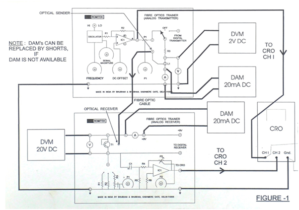
| FIBRE OPTICS COMMUNICATION LAB |
- Setting up of Fibre Optics Analog & Digital Link
- Measurement of frequency response of the Analog & Digital link
- To plot VI characteristic of photo transmitter & detector
- Study of loss in optical Fibres, measure NA, and generate & interpret eye diagrams.
|
| RADIO/TV LAB |
- Test the performance of the CTV receiver as Per relevant ISI
- Test the performance of the CTV receiver as Per relevant ISI
- Troubleshoot the CTV/BW receiver as per fault simulators given on the equipment.
|
| MICROWAVES COMMUNICATION LAB |
- To study the characteristics of the reflex Klystron tube
- To determine the frequency and wave length in a rectangular waveguide
- To determine the standing-wave-ratio and reflection coefficient
- To determine the unknown impedance
- To study the V – I characteristic of Gunn Diode
- The measure the polar pattern and the gain of a waveguide Horn antenna
- To plot the radiation pattern of different antennae
- To experimentally observe the function of all the microwave components provided
|
PHYSICS Lab
(Superconductivity) |
- Demonstration of The Meissner Effect, Frictionless Bearing, energy storage toroid and levitation
- Experiment on measuring the critical temperature using the Meissner effect using the four point electrical probe
- To obtain a plot resistance versus temperature
- Experiment on Determining the Critical Current Density
- Experiment on Determining the Critical Magnetic Field
- Plot of scusceptibility vs temp
|
PHYSICS Lab
Experiments on Wave Propogation of light |
- Study of diffraction using Plane Transmission Grating (for two incident wave lengths) and finding wavelength/ grating element
- Study of diffraction using Plane Reflection grating ( for two incident wave lengths) and finding wavelength/ grating element
- Study of Single Slit diffraction pattern and finding slit width
- Study of Pin Hole diffraction pattern and finding pin hole diameter
- Study of polarization
- Study of half wave & quarter plate properties
- Demonstration of strains in optical materials
- Study of Elliptically and Circularly polarized light
- Measurement of refractive Index of prism
- Measurement of Brewster angle of glass plate
- Demonstration of total internal reflection
- Verification of Snell’s law
- Measurement of wedge angle of a glass plate
- Setting up of Path Length Modulation System (Michelson Interferometer)
- Temporal coherence using Michelson interferometer
|
| PHYSICS LAB-OTHER EXPTS |
- Experiment on Addition of Forces by Vector Methods
- Experiment to verify the parallelogram law of vector addition by using a force table
- Experiment on equilibrium of concurrent force
- Experiment on Kinematics on an Inclined Plane
- Experiment on Speed of a Projectile
- Experiment on Newton’s Second Law
- Experiment on The Force of Gravity
- To show that a body launched horizontally will fall vertically at the same rate as a similar freely falling body.
- Experiment on Projectile Motion using Photo gates
- Experiment on Projectile Range versus Angle
|
| CONTROL SYSTEMS LAB |
- To determine the open loop transfer function of all the blocks viz. integrator, time constant, uncommitted amplifier and error detectors/adders experimentally
- To determine the first order (type 0 & type1) open loop system response for various input signals like unit step, ramp, square wave etc.
- To determine the closed loop response of first and second order systems.
- To study disturbance rejection of closed loop system
- Study of the relay characteristics and display of the same on CRO for different values of hysteresis and dead zones.
- Study of the effect of hysteresis on system stability
- Phase plane analysis of relay control system for various values of Hysterisis and Dead Zones.
- Operation of the position control system for different values of the forward gain to angular position commands
- Step response studies for various values of forward gain
- Study of the effect of velocity feedback on the transient and steady state performance of the system as well as its stability
|
| ELECTRICAL MACHINES LAB |
- Standard experiments like Torques Speed Characteristics, VI Characteristics, machine efficiency, protection mechanisms etc.
|
| APPLIED MECHANICS LAB |
|